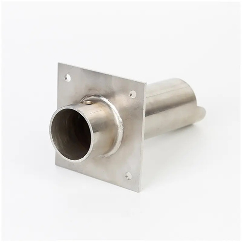
Turning of Copper Alloy Spindle Sliding Bearing Taper Sleeve
Copper alloy spindle bearing taper sleeves (referred to as copper alloy taper sleeves) are key components supporting the spindle’s rotation in equipment such as machine tools and steam turbines. Their tapered inner surface mates with the spindle’s tapered journal, allowing for axial adjustment of the clearance (typically controlled within 0.01-0.03mm). They offer strong load-bearing capacity and excellent vibration damping. Copper alloys (such as ZCuSn10P1 and ZCuPb15Sn8) possess excellent wear resistance and friction reduction, but their relatively low strength (tensile strength ≤300MPa) makes them susceptible to tool sticking and surface scratching during turning. In particular, the taper accuracy (tolerance ≤±0.005mm/m) and surface quality (Ra ≤0.8μm) of the conical surface are difficult to control. For example, when machining a copper alloy taper sleeve with a 1:30 taper, if the taper error exceeds 0.01mm/m, the spindle-bearing contact area will be less than 70%, leading to localized overheating and wear. Therefore, the turning of copper alloy tapered sleeves requires the development of special processes based on material properties and precision requirements.
The properties of copper alloys place special demands on turning processes. ZCuSn10P1 (tin bronze) offers excellent wear resistance but also exhibits high plasticity (elongation ≥10%). This can lead to chips easily wrapping around the tool during turning, forming built-up edge and increasing surface roughness (Ra values exceeding 3.2μm). ZCuPb15Sn8 (lead bronze), with its high lead content (15%), offers excellent cutting performance, but the lubricating effect of lead can accelerate tool wear, especially at high cutting speeds. Therefore, cutting tools should be made of hard alloys with sharp, low-friction properties (such as YG8 and YW1). YG8 is suitable for machining lead bronze due to its excellent wear resistance, while YW1 is suitable for machining tin bronze due to its strong anti-sticking properties. Tool geometry should include a large rake angle (15°-20°) and clearance angle (10°-12°) to reduce cutting forces and friction. A lead angle of 90°-93° should be used to prevent excessive radial forces and workpiece deformation. A nose radius of 0.2-0.5mm should be used to prevent surface tearing. A machine tool factory used YW1 tools to process ZCuSn10P1 tapered sleeves, and the surface roughness was reduced from Ra2.5μm to Ra0.8μm, and the built-up edge phenomenon was basically eliminated.
The turning method for conical surfaces must ensure taper accuracy and surface quality. Common methods include rotating the small slide method, offsetting the tailstock method, and wide-blade turning method: the rotating small slide method rotates the small slide by an angle equal to the half-angle of the taper (for example, the half-angle of a 1:30 taper is 0.959°), and is manually fed for turning. It is suitable for short taper sleeves (length <300mm) and has a taper accuracy of ±0.005mm/m. The offset tailstock method offsets the tailstock to form an angle between the workpiece axis and the spindle axis. It is suitable for long taper sleeves (length >500mm), but the taper accuracy is slightly lower (±0.01mm/m). The wide-blade turning method uses a wide-blade tool (blade width equal to the length of the taper surface) that matches the width of the taper surface to turn the taper surface in one go. It is efficient and has a smooth surface, making it suitable for mass production. The taper accuracy depends on the tool installation accuracy (≤±0.003mm/m). When turning, a trial cut is required first, followed by checking with a taper template or dial indicator. The tool angle should be adjusted based on the error (every 0.01mm/m error corresponds to a 0.001° adjustment of the small slide). A steam turbine plant used an “offset tailstock + fine turning correction” process to machine long taper sleeves with a 1:12 taper, keeping the taper error within 0.005mm/m, meeting the requirements for high-speed spindle operation.
Optimizing cutting parameters requires a balance between efficiency and surface quality. Cutting speeds for copper alloys can be higher than for steel: For rough turning, use 100-150 m/min (tin bronze) or 150-200 m/min (lead bronze), with a feed rate of 0.2-0.3 mm/r and a back-cut depth of 1-2 mm; for finish turning, use 200-300 m/min, a feed rate of 0.1-0.15 mm/r and a back-cut depth of 0.1-0.3 mm. High speeds can reduce built-up edge and improve surface quality. However, excessive speeds (>300 m/min) can cause surface oxidation (producing a black oxide film) on copper alloys and should be controlled within a reasonable range. Excessive feed rates can leave noticeable tool marks on the surface, while too low feed rates can prolong machining time. For surface requirements of Ra 0.8 μm, a feed rate of 0.12 mm/r or less is recommended. The depth of backcut should be considered based on the wall thickness of the tapered sleeve. For thin-walled sleeves (thickness < 5 mm), the single backcut should be ≤ 0.5 mm to avoid deformation. A precision instrument manufacturer achieved a stable surface roughness of Ra 0.4 μm for copper alloy tapered sleeves by optimizing parameters (finish turning speed 250 m/min, feed rate 0.1 mm/r), with a contact area exceeding 85%.
The clamping method and process must be adapted to the low strength of copper alloys. Copper alloy tapered bushings are often cast or forged blanks, so excessive clamping force should be avoided during clamping to prevent deformation. For thick-walled bushings (wall thickness ≥ 10mm ), a three-jaw chuck can be used for direct clamping, with a 0.5mm thick copper sheet between the jaws and the workpiece . For thin-walled bushings (wall thickness < 5mm ), an expansion clamp (for internal clamping) or a soft-jaw chuck is required, with the clamping force controlled to 20-30N · m using a torque wrench . The process follows the principle of " rough turning - annealing - semi-finish turning - finish turning." Process: After rough turning, stress relief annealing is performed ( ZCuSn10P1 is kept at 500-550 ℃ for 2 hours) to eliminate cutting stress; semi-finishing turning is performed with a 0.5-1mm margin to ensure the coaxiality of the inner and outer circles is ≤0.02mm; during finishing turning, the inner conical surface is first machined, and then the outer circle is machined using the conical surface as the positioning, ensuring the coaxiality of the conical surface and the outer circle is ≤0.01mm. Honing (using a 280# grinding wheel) is required after finishing turning to reduce the surface roughness to Ra0.2μm and remove burrs (edge radius R≤0.05mm). A machine tool spindle factory uses this process to control the assembly clearance of copper alloy taper sleeves to 0.0