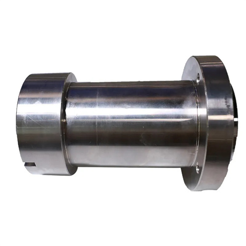
Turning of sleeve-type workpieces
Sleeve-type workpieces are common components in machining, such as bearing sleeves, bushings, and hydraulic cylinders. Their structural characteristics are characterized by an inner bore and an outer diameter, and most require geometric and positional tolerances such as coaxiality (≤0.02mm) and perpendicularity (≤0.01mm/m) between the end faces and the axis. The challenge in turning sleeves lies in maintaining these precision requirements while avoiding deformation of thin-walled sleeves. Sleeve-type workpieces are made of a variety of materials, including steel, cast iron, and non-ferrous metals. Turning thin-walled sleeves (thickness ≤3mm) is particularly challenging. Even slightly excessive clamping force can produce “ovality” (errors can reach over 0.1mm), and cutting heat can also cause dimensional accuracy to lose control. For example, when machining a φ50×φ45×100mm thin-walled sleeve made of 45 steel, improper processing can result in an inner bore cylindricity error exceeding 0.05mm, failing to meet shaft fit requirements. Therefore, turning sleeve-type workpieces requires systematic optimization of clamping methods, tool selection, and cutting parameters.
Choosing the right clamping method is key to controlling deformation of sleeve-type workpieces. For thick-walled sleeves (wall thickness ≥ 5mm ), a three-jaw self-centering chuck can be used to directly clamp the outer diameter. However, a copper sheet ( 0.5-1mm thick) should be placed between the jaws and the workpiece to prevent surface damage. The clamping force should be sufficient to prevent workpiece slippage (torque 30-50N · m ). Thin-walled sleeves require a special clamping method: For outer diameter clamping, an expansion clamp is used. Hydraulically actuated, the elastic sleeve is evenly expanded against the inner bore, distributing the clamping force across the entire inner surface and keeping deformation within 0.01mm . For inner bore clamping, a specialized external expansion chuck with fan-shaped jaws (contact area ≥ 80% ) is used to prevent localized crushing. For extra-long sleeves (aspect ratio > 10 ), a steady rest support is required. The support block is made of wear-resistant cast iron, and the contact pressure with the workpiece is adjusted to 0.02-0.03MPa using a dial indicator. After an automobile bearing factory used a tire expansion fixture to process thin-walled bearing sleeves, the roundness error of the inner hole was reduced from 0.08mm to 0.015mm, and the pass rate was increased to 99%.
The tool and parameter design for internal turning must balance precision and efficiency. The shank diameter of the internal turning tool should be as large as possible (0.6-0.7 times the hole diameter) to improve rigidity and reduce vibration. For example, when machining a φ50mm internal hole, the shank diameter should be ≥30mm. Tool material selection depends on the workpiece material: YT15 carbide is used for machining steel, YG8 for machining cast iron, and YW1 for machining non-ferrous metals. Regarding geometric parameters, a lead angle of 90°-93° reduces radial cutting forces; a rake angle of 10°-15° and a relief angle of 8°-12° ensure smooth cutting. For rough machining of internal holes, cutting speeds of 80-120 m/min, feeds of 0.2-0.3 mm/r, and back cut depth of 1-2 mm are recommended. For finishing, speeds of 100-150 m/min, feeds of 0.1-0.15 mm/r, and back cut depth of 0.1-0.3 mm are recommended. For blind hole machining, a chip flute is required at the front end of the tool to prevent chip clogging. The flute width is 8-10mm and the depth is 1.5-2mm. A hydraulic parts manufacturer used a carbide internal coolant tool to machine the inner bore of an 80mm diameter hydraulic cylinder. The result was a reduction in surface roughness from Ra3.2μm to Ra0.8μm, with straightness maintained within 0.02mm/m.
External and end-face turning must ensure positional accuracy relative to the inner hole. External turning is typically based on the machined inner hole (using a mandrel for positioning). The clearance between the mandrel and the inner hole is ≤0.005mm, ensuring coaxiality ≤0.01mm. A 90° external turning tool is used. High parameters (speed 100-150m/min, feed 0.3-0.5mm/r) are used for rough turning, and reduced parameters (speed 150-200m/min, feed 0.1-0.2mm/r) are used for finish turning. End-face turning must be perpendicular to the axis. A 45° turning tool can be used, with feed from the outer diameter toward the center to avoid leaving a boss at the center. Cutting speed decreases with decreasing diameter, requiring spindle speed compensation (such as the constant linear speed function on a CNC lathe). For sleeve-type workpieces with steps, the end faces should be turned first, followed by the external diameter. The flatness error of the step end faces should be ≤0.01mm. A certain engineering machinery factory has improved the coaxiality of sleeve-type workpieces from 0.03mm to 0.008mm through the process of “using inner holes to position outer circles”, meeting the requirements of high-precision matching.
Quality inspection and defect prevention for sleeve-type workpieces must be implemented throughout the entire machining process. Common defects include internal bore taper (caused by tool wear or uneven feed), ovality (deformation during clamping), and surface scratches (scratches caused by chips). Inspections include measuring the internal bore dimensions with an internal diameter dial indicator (accuracy ±0.001mm), checking roundness and coaxiality with a dial indicator, and checking surface quality with a roughness tester (Ra ≤ 1.6μm). For sleeve-type workpieces requiring sealing (such as hydraulic cylinder barrels), a hydrostatic test is required (at 1.5 times the operating pressure, maintaining pressure for 30 minutes to ensure no leakage). Preventative measures include regularly calibrating the machine tool spindle’s radial runout (≤ 0.005mm), sharpening the tool every 50 pieces to compensate for wear, and promptly clearing chips with compressed air to prevent accumulation and scratching of the surface. Through comprehensive quality control, a precision instrument manufacturer has increased the dimensional acceptance rate for sleeve-type workpieces from 90% to 99.8%, and reduced the customer complaint rate to below 0.1%.