Turning external conical surface
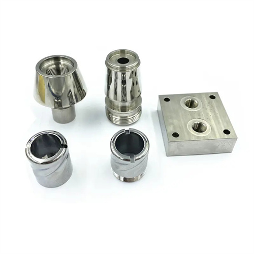
Turning external conical surfaces is a common process in mechanical machining. Its core is to ensure the taper accuracy and surface quality of the conical surface. Common processing methods include rotating the small slide method, offset tailstock method, profiling method and wide-blade knife turning method. Rotating the small slide method is one of the most commonly used methods. By rotating the small slide around the axis of the turntable by a certain angle, the tool moves along the center line of the conical surface, thereby turning the required conical surface. This method is simple to operate and is suitable for processing conical surfaces with a shorter length and larger taper, such as parts such as vertices and valve cores. The size of the rotation angle is equal to the half-angle of the cone, which needs to be calculated based on the taper of the cone. For example, a cone with a taper of 1:10 has a half-angle of approximately 2°51′45″. The angle needs to be precisely adjusted when rotating the small slide, which can be calibrated with the help of the dial or angle ruler on the turntable.
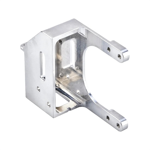
The offset tailstock method is suitable for machining external conical surfaces with longer lengths and smaller tapers, such as machine tool spindles and drive shafts. This method offsets the tailstock laterally relative to the spindle axis by a certain distance, so that the workpiece’s rotation axis forms an angle with the lathe spindle axis. This allows the tool to machine a conical surface during longitudinal feed. The calculation of the tailstock offset is related to the workpiece length, the large end diameter, and the small end diameter of the cone. The formula is: offset S = (Dd) L / (2L0), where D is the large end diameter, d is the small end diameter, L is the workpiece length, and L0 is the distance between the two centers. When using the offset tailstock method, it is important to note that the tailstock offset should not be too large, otherwise it will cause a large centrifugal force to be generated during the workpiece rotation, affecting machining accuracy and safety. It is generally suitable for machining conical surfaces with a taper of less than 1:20.
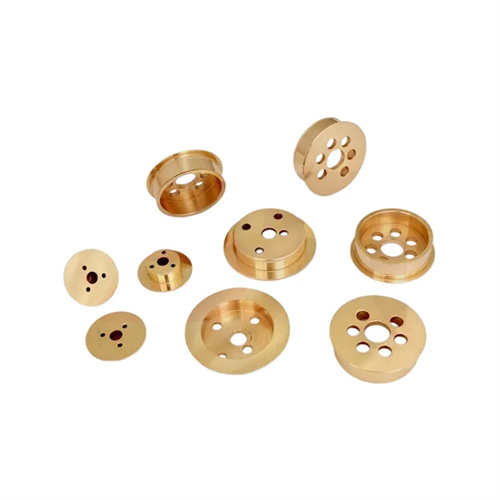
The profiling method (profiling method) is suitable for machining long conical surfaces in mass production. Its principle is to utilize a profiling device on the lathe bed, allowing the tool to feed longitudinally and transversely simultaneously, thereby turning the conical surface. The profiling device typically consists of a profiling plate, a slider, and a connecting rod. The profiling plate can rotate about a fulcrum, with an inclination angle equal to the cone’s half-angle. The slider slides on the profiling plate, driving the tool holder to move laterally via the connecting rod. The profiling method offers high machining efficiency and stable machining accuracy, making it suitable for machining batches of parts with the same taper. However, it requires a dedicated profiling device and is relatively complex to adjust. The broad-blade turning method uses a broad-blade tool with a blade width greater than the length of the cone’s generatrix to turn the conical surface in a single feed. This method is suitable for machining short, thick conical surfaces, such as bevel gear blanks. It requires good lathe rigidity and a straight tool edge. During installation, the blade must be strictly parallel to the cone’s generatrix, otherwise taper errors will occur.
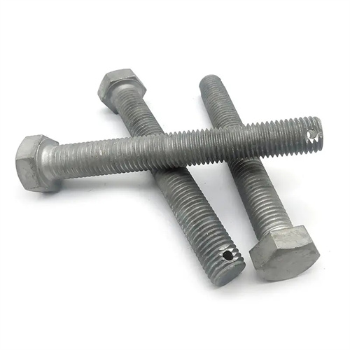
The selection of tools and the setting of geometric parameters for turning external conical surfaces have a significant impact on the processing quality. The tool material should be selected according to the workpiece material. When processing ordinary steel, high-speed steel or carbide tools can be used; when processing high-strength alloys or stainless steel, carbide or ceramic tools should be used. The geometric parameters of the tool must ensure smooth cutting . The front angle is generally 10°~15°, the back angle is 6°~10°, and the main deflection angle is determined according to the cone half angle and should be greater than the cone half angle to avoid friction between the tool back face and the workpiece surface. The blade inclination angle is 0°~5° to control the chip flow direction and avoid scratching the processed surface. In addition, the cutting edge of the tool must be sharp and can be properly ground to reduce cutting force and vibration and improve surface quality.
The cutting parameters and process measures for turning external conical surfaces also require proper control. The cutting speed is determined by the tool and workpiece materials. When machining ordinary steel with high-speed steel tools, the cutting speed should be 30-60 m/min; with carbide tools, the speed can be 80-150 m/min. The feed rate is generally 0.1-0.3 mm/r, with a lower value (0.05-0.15 mm/r) used for finish turning to ensure surface roughness. The cutting depth should be 1-3 mm for rough turning and 0.1-0.5 mm for finish turning. During machining, adequate cooling and lubrication are required, using emulsions or cutting oils to minimize tool wear and workpiece thermal deformation. For conical surfaces requiring high precision, rough turning, semi-finishing, and finishing turning should be performed separately. After rough turning, the taper and dimensions should be measured, and the tool position or small slide angle should be adjusted before semi-finishing and finishing turning. For finish turning, trial cutting can be used to measure the diameters of the large and small ends of the cone and gradually adjust the required dimensions to ensure accurate taper and a smooth surface.