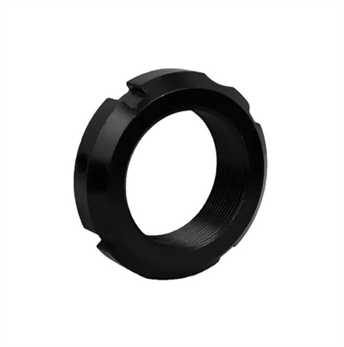
Common defects in gear hobbing and their elimination methods
Hobbing is one of the main methods of gear machining. The tooth profile is produced through the generating motion of the hob and the workpiece. Common defects include tooth profile error, pitch error, tooth direction error, surface roughness tolerance, and tooth gnawing. These defects will affect the meshing accuracy and service life of the gear. Tooth profile error refers to the deviation between the actual tooth profile and the theoretical involute. It manifests as an excessively large or small tooth profile angle, a pointed tooth top, and a thickened tooth root. The main causes include unqualified hob tooth profile accuracy, tilted hob installation, and improper cutting parameters. For example, wear of the hob will result in a smaller tooth profile angle, non-parallelism between the hob axis and the workpiece axis will cause the tooth profile to become skewed, and excessively high cutting speeds will cause irregular tooth profiles due to vibration.
Tooth pitch error includes pitch deviation and cumulative pitch error. Pitch deviation is the difference between the pitch of two adjacent teeth and the nominal pitch, and cumulative error is the sum of pitch deviations within a certain range. Pitch error is mainly caused by errors in the machine tool transmission chain. For example, wear of the indexing worm and indexing gear will lead to uneven indexing. If the workpiece is not clamped firmly and displacement occurs during processing, it will also cause pitch deviation. Uneven hob feed will cause the local pitch to become larger or smaller. Tooth direction error refers to the deviation in parallelism between the tooth surface contact line and the gear reference plane. It is mostly caused by machine tool guide rail straightness error, the workpiece axis is not parallel to the machine tool guide rail, the tailstock center is not coaxial with the spindle, etc. It manifests as a small contact area when the gears are meshing and severe local wear.
Excessive surface roughness is a common surface quality defect in gear hobbing, which manifests as ripples, scratches, scales, etc. on the tooth surface. The main reasons include blunt hob cutting edges, improper use of cutting fluid, and unreasonable cutting parameters. After the hob wears, the cutting force increases, and the tooth surface is prone to extrusion deformation, forming a rough surface; when processing plastic materials, if the cutting fluid is not lubricating enough, built-up edge will be generated, scratching the tooth surface; cutting speeds that are too low or feed rates that are too high will lead to an increase in the residual area of the tooth surface and an increase in the surface roughness value. Tooth gnawing refers to the appearance of deep grooves or gnawing marks on the tooth surface. It is a serious defect, mostly caused by sudden collision between the hob and the workpiece, failure of the machine tool feed system, loose workpiece clamping, etc. For example, sudden movement of the machine tool feed screw will cause the hob to scratch deep grooves on the tooth surface.
To eliminate tooth profile errors, first ensure the accuracy of the hob and select a hob that meets the requirements. Check the hob’s tooth profile and wear before use. Hobs with excessive wear should be sharpened or replaced promptly. When installing the hob, use a dial indicator to calibrate the parallelism between the hob axis and the workpiece axis, ensuring the error does not exceed 0.01mm/m. Adjust the hob’s installation angle to match the workpiece’s helix angle to avoid tooth profile skew due to angular deviation. Optimize cutting parameters. When machining steel, use a cutting speed of 80-120m/min and a feed rate of 0.5-1mm/r to reduce the impact of vibration on tooth profile. For high-precision gears, a precision rolling process can be used, leaving a margin of 0.05-0.1mm. Use a high-precision hob for precision rolling to reduce tooth profile errors.
Eliminating pitch errors requires addressing both machine tool accuracy and clamping. Regularly inspect and repair the machine tool drive chain, replace worn indexing worms, gears, and other parts to ensure indexing accuracy. Adjust the machine tool feed system to ensure uniform and stable feed rates. When clamping the workpiece, use a rigid fixture, such as a three-jaw chuck with a center, or a clamping sleeve for thin-walled gears, to prevent the workpiece from loosening during machining. Correct the workpiece’s radial runout and end runout to within 0.01-0.02mm. During machining, regularly measure pitch deviation with a pitch gauge. If cumulative errors exceed tolerance, adjust the machine tool drive chain clearance promptly.
For excessive surface roughness, maintain a sharp hob cutting edge. Finely grind the hob before finishing hobbing, maintaining a cutting edge roughness below Ra0.4μm. Select the appropriate cutting fluid based on the workpiece material: extreme pressure emulsion for steel and kerosene for cast iron, ensuring adequate lubrication and cooling. Optimize cutting parameters, using a higher cutting speed (100-150 m/min) and a lower feed rate (0.3-0.5 mm/r) during finishing hobbing to reduce residual area on the tooth surface. To prevent tooth gnawing, inspect the machine tool feed system before machining to ensure the lead screw and nut are free of looseness or movement. Ensure the workpiece is securely clamped to avoid sudden forces. Use a slow feed when the hob enters the workpiece to minimize impact. These measures can effectively eliminate common hobbing defects and improve gear machining quality.