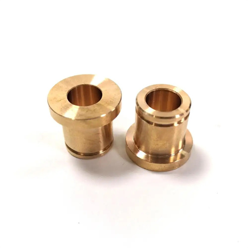
Metal cutting process
The metal cutting process is a physical process in which the relative motion between the tool and the workpiece causes the cut layer of metal to undergo plastic deformation and peel off into chips. It involves the intersection of multiple disciplines, including mechanics, thermodynamics, and materials science. The process can be divided into three stages: the elastic deformation stage (the metal in the cut layer is squeezed by the tool, producing elastic compression), the plastic deformation stage (the material reaches its yield limit and slides along the shear plane), and the fracture separation stage (the metal separates from the workpiece after sliding, forming chips). Taking 45 steel turning as an example, when the tool rake angle is 10° and the cutting speed is 100m/min, the strain in the plastic deformation zone can reach 2-5, and the strain rate can reach 10^3-10^4s^-1, which is much higher than the deformation rate in ordinary material testing. Material behavior under these extreme conditions is key to determining cutting quality.
The generation and distribution of cutting forces directly impact machining stability. Cutting forces can be decomposed into three components: the main cutting force Fc (along the cutting speed), the feed resistance Ff (along the feed direction), and the back force Fp (perpendicular to the feed direction). The main cutting force accounts for 70%-80% of the total cutting force and is the primary factor affecting tool wear and machine power consumption. Cutting force magnitude is closely related to workpiece hardness, cutting parameters, and tool angle. Increasing the hardness of 45 steel from HB200 to HB300 increases cutting force by 20%-30%. Increasing back engagement from 1mm to 3mm results in a nearly linear increase in cutting force (approximately a 2-fold increase). Increasing the rake angle from 5° to 15° reduces cutting force by 10%-15%. Real-time monitoring of these force components using a cutting force meter (such as a piezoelectric dynamometer) can determine tool wear status (a sudden increase in Fp by more than 30% typically indicates flank wear exceeding 0.3mm), providing a basis for adaptive control.
The classification and control of chip morphology are crucial areas of research in the metal cutting process. Based on the degree of plastic deformation and appearance, chips can be categorized as ribbon chips (continuously curled, suitable for materials with good plasticity, such as low-carbon steel), nodular chips (semi-continuous, suitable for medium-carbon steel), granular chips (discrete particles, suitable for high-carbon steel), and chip-crushing chips (brittle fracture, suitable for cast iron). While ribbon chips offer smooth cutting, they tend to wrap around the tool and workpiece. Therefore, the tool’s chip flutes (8-15mm width, 1-3mm depth) must be used to control the curling radius (typically 5-10mm) and break them into C-shaped or figure-6 chips. For high-strength alloy steels, negative chamfering tools (0.1-0.3mm width, -5° to -10° angle) can be used to increase the chip’s resistance to deformation and promote fracture. The color of the chips can reflect the cutting temperature: silvery white (<200℃), light yellow (200-300℃), dark blue (300-400℃), gray-black (>400℃). When the color is dark blue or above, be alert to tool overheating and wear.

The distribution and transfer of cutting temperature significantly impact tool life. The highest temperature in the cutting zone occurs at the contact area between the tool rake face and the chip (approximately 0.1-0.2mm from the cutting edge), reaching 800-1000°C (when machining medium-carbon steel). The tool absorbs 10%-20% of this heat, the workpiece absorbs 20%-30%, and the chips carry away 50%-70%. Rising temperatures cause the hardness of the tool material to decrease: carbide tools lose 20% of their hardness above 600°C, while ceramic tools can withstand temperatures exceeding 1200°C. Cooling and lubrication technologies can effectively control temperature: emulsions (5%-10% concentration) reduce cutting zone temperatures by 30%-40% through convection; extreme pressure cutting oils (containing sulfur and phosphorus additives) form a chemical lubricating film on the tool surface, reducing frictional heat generation. For dry cutting (occasions with high environmental protection requirements), PCBN tools should be selected, combined with high-speed cutting (300-500m/min), to use the chips to quickly remove heat and keep the workpiece temperature below 150℃.
Quality control in the metal cutting process requires comprehensive optimization of process parameters. Surface roughness is primarily determined by tool geometry and feed rate: when the feed rate decreases from 0.3mm/r to 0.1mm/r, the surface roughness Ra value can be reduced from 3.2μm to 0.8μm; increasing the tool tip radius from 0.4mm to 1.2mm can reduce the Ra value by 50%. The depth of the work-hardened layer (typically 0.05-0.3mm) is proportional to the cutting force. The degree of hardening can be reduced by reducing the back cut and increasing the cutting speed. For precision machining (such as IT5 grade precision), it is necessary to control residual stress in cutting. A symmetrical cutting path (such as bidirectional cutting) and low-temperature cutting (cooling from -50 to -100°C) are used to keep residual stress within 50MPa. In the machining of an aircraft engine blade, optimizing cutting parameters (vc = 200 m/min, f = 0.1 mm/r, ap = 0.5 mm) improved surface roughness from Ra1.6 μm to Ra0.4 μm, extending fatigue life by 30%. In the future, combining cutting process prediction technology with finite element simulation (such as AdvantEdge software) will enable pre-machining parameter optimization, reducing the number of trial cuts and lowering production costs.