Turning of deformed workpieces
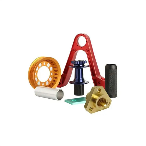
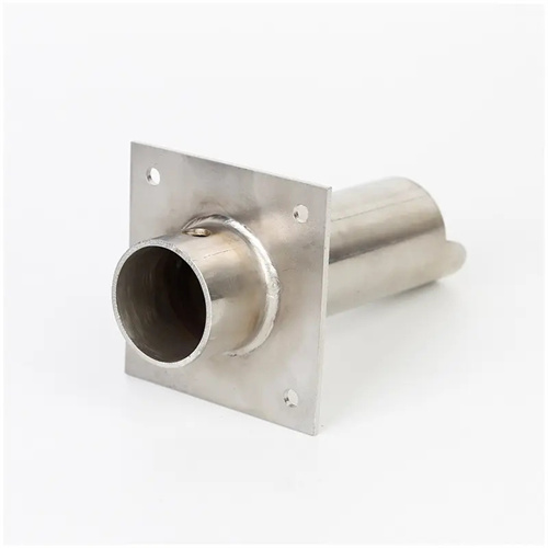
Deformed workpieces, such as eccentric shafts, crankshafts, and special-shaped brackets, are irregularly shaped and complex, making them difficult to machine using conventional clamping methods. Turning these workpieces, often challenging in mechanical manufacturing, presents a significant challenge. Due to their asymmetrical shapes and center of gravity offset from the center of rotation, these workpieces are prone to vibration and deformation during machining. This not only affects machining accuracy and surface quality, but can also lead to increased tool wear and equipment damage. Therefore, turning deformed workpieces requires a rational machining process, specialized clamping tools, optimized cutting parameters, and effective quality control measures to ensure process stability and ultimate part performance.
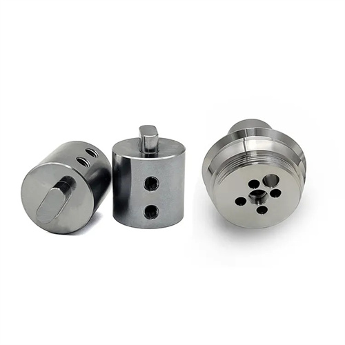
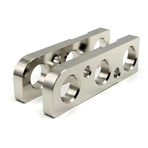
Innovative clamping design is key to turning deformed workpieces. Due to the irregular shapes of deformed workpieces, traditional three- and four-jaw chucks often cannot meet the clamping requirements, necessitating specialized fixtures tailored to the workpiece’s structural characteristics. For example, for workpieces with eccentric shafts, eccentric chucks or double-center clamping can be used. Eccentric chucks maintain workpiece eccentricity by adjusting the eccentricity, while double-center clamping minimizes clamping distortion by machining center holes at both ends of the workpiece and using the center support and dial to rotate the workpiece. For workpieces with flat or curved surfaces , faceplate clamping can be used. Faceplates feature multiple T-slots, allowing for the attachment of auxiliary tools such as angle irons, pressure plates, and locating blocks, tailored to the workpiece’s shape, ensuring precise positioning and secure clamping. During the clamping process, alignment is required using a dial indicator or marking to ensure that the workpiece’s rotation center aligns with the lathe spindle axis or meets specific eccentricity requirements. Alignment error should generally be controlled within 0.02-0.05mm to ensure machining accuracy.
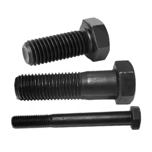
The proper selection of cutting tools significantly impacts the turning quality of deformed workpieces. Due to the complex forces acting on deformed workpieces during machining, cutting tools must not only withstand high cutting forces but also adapt to the changing shape of the workpiece. Therefore, the tool material and geometry must be specifically designed. For deformed workpieces with poor rigidity, sharp high-speed steel or coated high-speed steel cutting tools should be used to reduce cutting forces and prevent workpiece deformation. For example, when machining thin-walled, irregularly shaped parts, tungsten-cobalt carbide cutting tools can be used with a rake angle of 10°-15° and a relief angle of 6°-8° to reduce cutting resistance. For deformed workpieces with high strength and hardness, such as quenched irregular cams, cubic boron nitride (CBN) or ceramic cutting tools should be used to improve wear resistance and high temperature resistance, ensuring a stable cutting process. Furthermore, the tool shank should possess sufficient rigidity to prevent ripples or chatter marks on the machined surface caused by shank deformation. The shank cross-sectional dimensions should be determined based on the cutting forces; generally, the shank diameter should be no less than 1.5 times the diameter of the cutting portion of the tool.
Optimizing cutting parameters is crucial for ensuring turning efficiency and quality when machining deformed workpieces. Due to the poor clamping rigidity of deformed workpieces, vibration is easily generated during machining. Therefore, the cutting speed should not be too high, generally controlled at 50-100 m/min. For easy-to-cut materials such as non-ferrous metals, this can be appropriately increased to 100-150 m/min, while for high-strength alloys, it should be reduced to 30-50 m/min. The feed rate should be selected based on the workpiece’s precision requirements and surface quality. A higher feed rate (0.2-0.5 mm/r) can be used for roughing to improve machining efficiency and remove most of the excess stock; a lower feed rate (0.05-0.1 mm/r) is required for finishing to ensure surface roughness. Back-cutting should be performed in layers, with each cut not exceeding a maximum depth, generally 0.5-2 mm, to avoid workpiece loosening or deformation due to excessive cutting forces. During the turning process, the cutting parameters must be adjusted in time according to the changes in the workpiece shape. For example, when turning curved surfaces or steps, the feed rate and back cutting depth should be appropriately reduced to ensure smooth cutting.
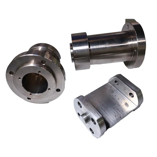
A well-planned process path is crucial for the turning accuracy of deformed workpieces. Machining deformed workpieces typically requires multiple steps, and the principle of “roughing first, finishing second, primary machining second, and surface machining first, then hole machining” should be adhered to, gradually improving part accuracy. Rough machining begins by removing scale and most excess material from the blank’s surface, correcting for shape errors, and laying the foundation for subsequent machining. Semi-finishing machining then processes primary and secondary surfaces, bringing the part’s dimensions and shape closer to design requirements. Finally, finishing machining ensures the accuracy and surface quality of critical surfaces. For deformed workpieces requiring heat treatment, heat treatment should be performed after rough machining and before semi-finishing to eliminate internal stresses and prevent excessive deformation after heat treatment. Necessary inspections and corrections are also required between steps. For example, after rough machining, check the workpiece’s clamping accuracy and shape errors, and adjust fixtures or tools promptly to ensure accuracy in subsequent machining. Furthermore, for deformed workpieces with complex structures, segmented or combined machining can be employed, breaking the complex part into simpler units that can be machined separately before assembly, reducing machining complexity.
Quality control and safety precautions are crucial aspects of the turning process for deformed workpieces. Due to the irregular shapes of deformed workpieces, problems such as dimensional deviations, deformation, and surface damage are prone to occur during machining. Therefore, enhanced in-process inspection is essential. Tools such as vernier calipers, micrometers, dial indicators, and coordinate measuring machines should be used to regularly check the workpiece’s dimensional and shape accuracy to promptly identify and resolve any issues. First-article inspection should be conducted for critical processes to confirm that the process parameters and clamping methods are correct before mass production begins. Regarding safety precautions, the clamping of deformed workpieces must be secure and reliable to prevent accidents caused by flying workpieces during machining. Protective shields should be installed during turning to prevent flying chips and injuries. Operators should wear protective equipment such as hard hats, safety glasses, and gloves. Furthermore, regular inspections of lathe and fixture performance are necessary to ensure proper operation and accurate fixture positioning to prevent equipment failures from impacting machining quality and production safety. Strict quality control and safety precautions are essential to ensure a smooth turning process for deformed workpieces and produce high-quality parts that meet design requirements.