Plane machining allowance
Plane machining allowance refers to the thickness of the metal layer removed from the blank surface to the finished part during planar machining. Its proper determination directly impacts part quality, production efficiency, and manufacturing costs. Excessive machining allowance increases cutting time and material consumption, exacerbating tool wear (for example, increasing the allowance from 2mm to 5mm can reduce tool life by 40%). Excessive machining allowance fails to eliminate surface defects (such as scratches and scale) and form errors (such as flatness) from the preceding process, leading to increased scrap rates. For example, insufficient total allowance during planar machining of a gray cast iron machine tool bed can leave sand holes and air holes, affecting the wear resistance of subsequent guideways. Excessive machining allowance not only increases machining time but can also cause deformation of the bed due to excessive cutting forces. Therefore, the determination of planar machining allowance should comprehensively consider the blank type, the accuracy of the preceding process, material properties, and part precision requirements, adhering to the principle of “sufficient but minimum.”
The type of blank and the manufacturing method are the basis for determining the total allowance for planar machining. The surface quality and precision of different blanks vary significantly, and the required total machining allowance also varies. For cast blanks (such as iron castings), which have a rough surface (Ra 50-100μm) and casting defects (such as scale and pores), a total allowance of 3-10mm is required, with 1-2mm of the first cut required to remove surface defects. For forged blanks (such as steel forgings), which have scale and forging cracks, a total allowance of 2-8mm is required, and cutting must be done along the forging flow line to prevent crack propagation. For hot-rolled steel plate blanks, which have a relatively smooth surface (Ra 12.5-25μm), a total allowance of 1-3mm is required. For cold-rolled steel plate blanks, which have a high precision (Ra 3.2-6.3μm), a total allowance of 0.5-1mm can be controlled. For precision casting or powder metallurgy blanks, due to their high precision (dimensional error ±0.1-0.3mm), the total allowance can be reduced to 0.3-0.5mm, or even proceed directly to finish machining. A machine tool factory uses the allowance distribution of “rough milling (5mm) – semi-finishing milling (2mm) – finishing milling (0.5mm)” for gray cast iron bed, which not only eliminates casting defects but also ensures the final flatness (≤0.03mm/m).
The allocation of machining allowances between processes must follow a “gradually decreasing” principle to ensure machining quality and efficiency in each process. The primary task of the roughing stage is to remove the majority of the allowance (70%-80% of the total allowance). The allowance is typically 1-5 mm. High cutting parameters (such as a milling speed of 100-200 m/min and a feed of 0.3-0.5 mm/z) are employed to improve efficiency, with lower surface quality requirements (Ra 12.5-25 μm). The semi-finishing stage removes the errors and hardened layers left by roughing. An allowance of 0.5-2 mm is used, with moderate cutting parameters (speed of 150-300 m/min and feed of 0.1-0.3 mm/z) to achieve a surface quality of Ra 3.2-6.3 μm. The finishing stage ensures ultimate precision and surface quality, with an allowance of 0.1-0.5mm and low cutting parameters (speed 200-400m/min, feed 0.05-0.1mm/z) employed. Surface roughness Ra 0.8-3.2μm is achieved. For high-precision surfaces (such as precision guide rails), additional finishing operations (such as grinding and scraping) are required, with an allowance of 0.01-0.1mm, achieving a surface roughness of Ra 0.02-0.8μm. The top surface of an automobile engine block is machined using a “rough milling (3mm) – semi-finishing milling (1mm) – finishing milling (0.3mm) – honing (0.05mm)” allowance distribution, achieving a flatness of 0.01mm/m, meeting sealing requirements.
Factors influencing plane machining allowances must be comprehensively considered to ensure appropriate allowance settings. The surface roughness and defect layer depth of the preceding process are key factors. For example, if the surface roughness after rough milling is Ra12.5μm and the defect layer (oxidation and decarburization layer) is 0.1-0.2mm deep, a semi-finishing allowance of 0.3mm or greater is required to completely remove it. Form errors (such as flatness and perpendicularity) in the preceding process also need to be compensated for using allowances. For example, if the flatness error after rough machining is 0.2mm, the semi-finishing allowance should be 0.2mm or greater. Workpiece deformation also needs to be considered. For example, if the deformation of a casting after aging is 0.1mm, 0.1-0.15mm should be included in the allowance. Furthermore, clamping errors (such as workpiece positioning errors in the fixture) will also affect the actual allowance, typically requiring an additional compensation of 0.05-0.1mm. The comprehensive calculation formula is: Process allowance = Surface roughness of the preceding process + Defect layer depth + Form error + Deformation + Clamping error. In the machining of a precision part, by accurately calculating various factors, the semi-finishing milling allowance was reduced from 0.8mm to 0.5mm, improving machining efficiency by 30% without any quality issues.
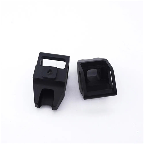
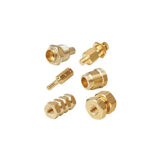
Different materials have different planar machining allowance characteristics, requiring targeted adjustments. Non-ferrous metals (such as aluminum and copper alloys) have good plasticity and are prone to built-up edge during machining. Therefore, a slightly larger roughing allowance (1-3mm) is required to avoid residual defects; however, a smaller finishing allowance (0.1-0.3mm) is required to prevent surface tearing.