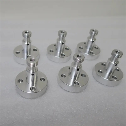
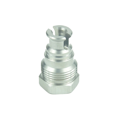
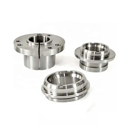
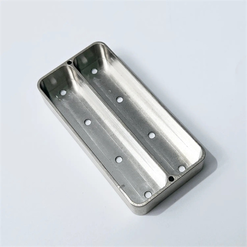
Turning of aluminum alloy sleeve
Aluminum alloy sleeves are commonly used components in aerospace, automotive, and precision instrumentation. They offer advantages such as light weight, excellent thermal conductivity, and strong corrosion resistance. However, turning them presents challenges such as tool sticking, surface burrs, and difficulty controlling dimensional accuracy. Aluminum alloys have a low hardness (HB50-100) and good plasticity. During cutting, chips easily wrap around the tool, forming a built-up edge (BUE), which increases surface roughness (Ra values exceeding 3.2μm). For example, when machining a 6061 aluminum alloy sleeve (φ50×100mm), improper processing can result in an inner bore cylindricity error exceeding 0.03mm, failing to meet mating requirements. Therefore, turning aluminum alloy sleeves requires optimization of tool selection, cutting parameters, cooling and lubrication, and clamping methods to ensure machining quality and efficiency.
The choice of tool material and geometry plays a decisive role in the turning quality of aluminum alloy sleeves. Due to the high plasticity and low hardness of aluminum alloys, sharp tools with a low friction coefficient are required to avoid sticking and built-up edge. High-speed steel tools (such as W18Cr4V) have sharp cutting edges and are suitable for machining thin-walled sleeves with high precision requirements. However, they have poor wear resistance and cutting speeds should not exceed 100 m/min. Carbide tools (such as WC-Co alloys with a Co content of 10%-15%) offer better wear resistance and can reach cutting speeds of 200-400 m/min, making them suitable for mass production. Ultrafine-grained carbide (grain size 0.5-1 μm) has a cutting edge sharpness approaching that of high-speed steel, making it an ideal choice for balancing efficiency and quality. Tool geometry requires a large rake angle (15°-20°) and clearance angle (10°-12°) to reduce cutting forces and friction. A lead angle of 90°-93° reduces radial forces and prevents deformation of thin-walled sleeves. A tool tip radius of 0.2-0.5mm prevents surface tearing. In one case, using a carbide tool with a rake angle of 20° and a clearance angle of 12° reduced the surface roughness of an aluminum alloy from Ra2.5μm to Ra0.8μm, virtually eliminating built-up edge.
Optimizing cutting parameters requires balancing machining efficiency and surface quality. Aluminum alloys have a thermal conductivity 3-5 times that of steel (approximately 120-200 W/(m・K) ). Cutting heat is easily carried away by the chips, so high cutting speeds can improve efficiency: for rough turning, use a speed of 200-300 m/min , a feed of 0.2-0.3 mm/r , and a back-cut of 1-2 mm ; for finish turning , use a speed of 300-400 m/min , a feed of 0.1-0.15 mm/r , and a back-cut of 0.1-0.3 mm . High cutting speeds quickly free chips from the tool, reducing the risk of tool sticking. Experimental results show that increasing the speed from 100 m/min to 300 m/min reduces the incidence of built-up edge from 80% to below 5% . However, excessively high speeds (over 500 m/min) can increase tool wear, so appropriate settings should be tailored to the tool material. Excessive feed rate will cause obvious tool marks on the surface, while too little will affect efficiency. For surface requirements of Ra0.8μm, the feed rate should be controlled within 0.1mm/r. The selection of back cutting depth should take into account the sleeve wall thickness. For thin-walled parts (wall thickness < 2mm), the single back cutting depth should not exceed 0.5mm to avoid deformation.
Cooling, lubrication, and chip evacuation are key to aluminum alloy sleeve turning. Aluminum alloy cutting requires the use of specialized cutting fluids (such as emulsions with a 5%-8% concentration or kerosene) to cool the tool, lubricate the cutting zone, prevent tool sticking, and flush away chips. Ordinary emulsions lack lubricity, which can lead to accelerated tool wear. Therefore, oil-based additives (such as fatty acid esters) are added to strengthen the lubricating film. For internal turning, a high-pressure coolant system (0.3-0.5 MPa) is required, with the cutting fluid introduced into the hole through specialized nozzles to ensure adequate cooling. Poor chip evacuation can cause chips to scratch the machined surface, so the tool’s chip flute design must be optimized. External turning tools should utilize wide, shallow flutes (8-12 mm wide and 1-2 mm deep) to direct chips outward. Internal turning tools should have their flutes angled toward the shank to prevent chips from clogging the bore. After an automotive parts factory adopted high-pressure cooling + spiral chip groove tools, the surface scratch rate of the aluminum alloy sleeve dropped from 15% to below 1%.
The clamping method and process route need to adapt to the structural characteristics of the aluminum alloy sleeve. Thin-walled aluminum alloy sleeves (wall thickness 1-3mm) have poor rigidity and are prone to deformation during clamping. The radial clamping force of traditional three-jaw chucks can cause the workpiece to be “flattened” and the roundness error can reach more than 0.1mm. Improvement plans include: using a soft-jaw chuck (the soft jaws are made of aluminum alloy or copper), turning the soft jaws to make the clamping surface completely fit the outer circle of the workpiece, reducing local stress; using an expansion clamp (internal hole clamping) to convert radial force into uniform axial force, and the roundness error can be controlled within 0.01mm; for extra-long sleeves (length-to-diameter ratio > 5), a tool holder or center frame is required, and the support points are made of nylon material to avoid surface damage. The process follows a “rough turning – aging – finish turning” process: After rough turning, stress relief aging (holding at 120-150°C for 2 hours) is performed to eliminate cutting stresses. Finish turning begins with machining the inner hole, then uses the hole as positioning for machining the outer diameter, ensuring coaxiality (≤0.01mm). By optimizing clamping and processes, an aviation parts manufacturer has improved the dimensional accuracy of aluminum alloy sleeves from IT10 to IT7, achieving a 99% pass rate.
Quality control and defect prevention must be implemented throughout the entire machining process. Common defects of aluminum alloy sleeves include surface scratches, dimensional deviations, deformation, and burrs, requiring targeted prevention measures. Surface scratches can be addressed by enhancing chip removal and cleaning, with tools and fixtures cleaned every 10 pieces. Dimensional deviations require regular machine calibration (daily first-piece inspection) and lead screw backlash compensation (controlled to within 0.005mm). Deformation can be minimized by low-temperature finish turning (cutting fluid temperature 15-20°C). Burrs require post-finish turning deburring (e.g., electrolytic deburring or manual sanding with fine sandpaper) to ensure edge radius R ≤ 0.05mm. Inspection procedures include measuring the internal bore dimensions with an internal micrometer (accuracy ±0.001mm), checking roundness and coaxiality with a dial indicator, and checking the Ra value with a surface roughness tester. For critical components, eddy current testing is also required to detect microcracks caused by tool sticking. A precision instrument factory reduced the scrap rate of aluminum alloy sleeves from 8% to 0.5% through comprehensive quality control, significantly reducing production costs.