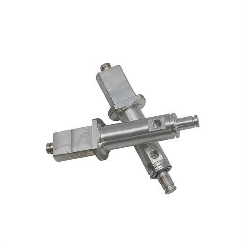
The serrated thread screw is a key component in mechanical transmission that withstands unidirectional axial forces. Its thread profile is serrated, with one side being the working surface (3° inclination) and the other side being the non-working surface (30° inclination). It is widely used in heavy equipment such as presses and rolling mills. When turning this type of screw, the contact accuracy of the working surface and the consistency of the thread lead must be ensured, otherwise it will lead to a decrease in transmission efficiency or increased local wear. Taking the Tr40×10 serrated thread as an example, the tooth side angle tolerance of its working surface must be controlled within ±15′, and the lead error must not exceed 0.02mm/100mm, which places strict demands on the processing technology. The turning process needs to take into account the thread profile accuracy, surface quality and overall rigidity of the screw, so it requires systematic planning from aspects such as tool design, clamping method, and cutting parameters.
Tool geometry design is crucial for ensuring the accuracy of serrated thread profiles. Due to the significant difference in profile angles between the two sides of a serrated thread, specialized forming turning tools are required, with cutting edge shapes that precisely match the thread profile. Tool material selection should be determined by the screw material. When machining quenched and tempered steels like 45 steel, W18Cr4V high-speed steel tools are used. After sharpening, they produce a sharp cutting edge and ensure surface roughness on the working surface. When machining high-strength alloy screws like 38CrMoAlA, TiAlN-coated carbide tools (such as WC-Co alloy) with a hardness of HRC65 or higher are required to resist wear under high cutting forces. The tool rake angle should be between 0° and 5° to avoid profile angle errors caused by excessive rake angles. The clearance angle should be between 6° and 8° to minimize friction between the flank and the thread flank. To ensure the straightness of the 3° working surface, the tool edge straightness error must be ≤0.01mm/100mm, which can be achieved using an optical profile grinder. A case study shows that the thread profile replication accuracy was improved from 0.03mm to within 0.01mm by using a special profile-ground tool.
The clamping method and process must be tailored to the screw’s aspect ratio. Sawtooth-threaded screws typically have an aspect ratio of 15-30, making them slender and relatively rigid. Clamping requires a “one-clamp, one-support” approach with a steady rest. A three-jaw chuck is used for light clamping on the spindle (the clamping force should be sufficient to prevent workpiece slippage), while a dead center is used on the tailstock to prevent axial movement. The steady rest is mounted on a slide box, and the contact pressure between the support jaws and the outer diameter of the screw must be adjusted to 0.01-0.02 MPa using a dial indicator to offset radial cutting forces. The process follows a “rough turning – tempering – semi-finishing turning – finish turning” process. During rough turning, a 2-3mm machining allowance is reserved, and straight-line cutting is used to quickly remove the stock. After tempering (e.g., 45 steel tempered to HB220-250), the outer diameter and thread root diameter are semi-finished to ensure radial dimensional accuracy. Finish turning the threads utilizes a left-right cutting method, first turning the 30° non-working surface, then the 3° working surface, and finally finish turning the thread tops and roots. For multi-start serrated threads, precise line division is required using a graduated dial with a line division error of ≤0.01mm to ensure consistent lead across the helical threads.
Optimizing cutting parameters requires balancing machining efficiency and quality. For rough turning, use a lower cutting speed (50-80 m/min), a higher feed rate (0.3-0.5 mm/r), and a 1-2 mm back-cut to improve efficiency. For finish turning, reduce the cutting speed to 30-50 m/min, feed rate 0.1-0.2 mm/r, and 0.1-0.3 mm back-cut to ensure surface quality. Because the 3° working surface is a stress-bearing surface, finish turning requires multiple passes, checked with a thread gauge after each pass, until the thread profile fits ≥80%. The cutting fluid is an extreme pressure emulsion (containing sulfur and phosphorus additives) at a concentration of 10%-12%. It is sprayed into the cutting zone through a high-pressure nozzle (0.4 MPa) to reduce tool wear and flush away chips. Stopping the machine mid-process should be avoided to prevent tool marks on the thread surface. Experimental data show that when the finishing speed is reduced from 60m/min to 40m/min, the thread surface roughness Ra value is reduced from 1.6μm to 0.8μm, and the tool life is extended by 50%.
Quality inspection and error correction mechanisms are crucial to ensuring lead screw performance. After threading is completed, three key indicators must be checked: Check the thread profile for fit using a serrated thread gauge to ensure smooth insertion of the go gauge and no-go gauge insertion of no more than three threads; measure the lead error using a lead gauge to ensure the cumulative error along the entire length is ≤0.1mm; and check the working surface Ra value using a surface roughness tester to ensure the Ra value is ≤1.6μm. Excessive lead error can be corrected by adjusting the lathe screw’s axial play (controlled to 0.01-0.02mm) or modifying the tool feed compensation value. Excessive thread angle error requires resharpening the tool and calibration using a template. After processing, the lead screw must undergo an aging treatment (at 200°C for four hours) to eliminate cutting stress and prevent deformation during use. By establishing a closed-loop “processing-inspection-correction” system, a heavy machinery plant has increased the qualified rate of serrated thread screws from 82% to 99%, extending their service life by more than two times.