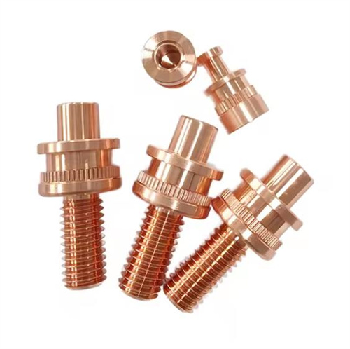
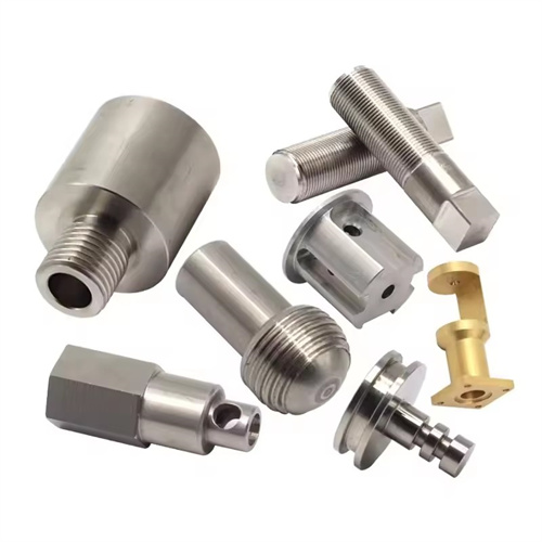
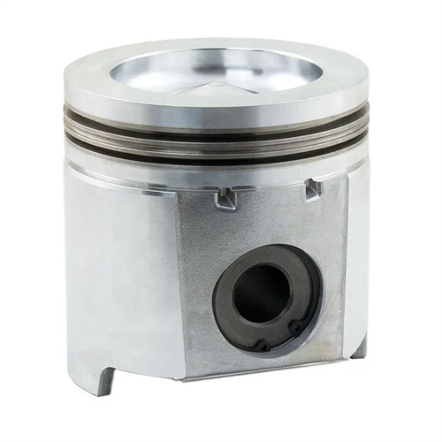
Turning of zinc alloy
Zinc alloys are non-ferrous metals based on zinc with alloying elements such as aluminum, copper, and magnesium. They offer advantages such as low density (6.6-6.9 g/cm³), excellent casting properties, and low cost, making them widely used in automotive parts, electronic housings, and toy components. However, turning zinc alloys present unique challenges: low strength (tensile strength 100-300 MPa) and low hardness (HB60-100), which can easily cause tool sticking and build-up edge during turning. Furthermore, the material has poor plasticity, resulting in fragmented chips that can easily clog the cutting zone and affect surface quality. For example, when machining zinc alloy die-castings, improper tool selection can result in surface tearing or scratching, with roughness values exceeding 3.2 μm. Therefore, turning zinc alloys requires a tailored process tailored to the material’s properties, including tool selection, cutting parameters, and cooling methods.
The choice of tool material and geometry must be tailored to the low strength of zinc alloys. For rough turning, tungsten-cobalt carbides (such as YG8 and YG6) are recommended. Their excellent toughness and moderate wear resistance prevent tool chipping, and their low affinity with zinc reduces tool sticking. For finish turning, surface quality must be ensured by using sharp high-speed steel tools (such as W18Cr4V) or ultrafine-grain carbides (such as YG3X), with a ground edge roughness of Ra ≤ 0.02μm to avoid scratching the workpiece. Tool geometry requires large rake angles (15°-20°) and clearance angles (10°-15°) to reduce cutting forces and friction; a leading rake angle of 90°-93° to prevent workpiece deformation; and a tool tip radius of 0.1-0.3mm to prevent surface tearing. For complex zinc alloy parts (such as slotted housings), high-speed steel forming tools are recommended to form multiple surfaces simultaneously, reducing tool changes and positioning errors. An electronics factory used YG6 cutting tools to process zinc alloy mobile phone casings, reducing the surface roughness from Ra2.5μm to Ra0.8μm and basically eliminating the tool sticking phenomenon.
Optimizing cutting parameters requires a balance between efficiency and surface quality. Cutting speeds for zinc alloys can be significantly higher than those for steel: 200-300 m/min for rough turning, utilizing high-speed cutting to reduce tool-workpiece contact time and mitigate the risk of tool sticking; 300-400 m/min for finish turning, utilizing a “high-speed ironing” effect to improve surface quality. Feed rates should be adjusted based on surface requirements: 0.15-0.3 mm/r for rough turning to quickly remove excess stock; 0.05-0.1 mm/r for finish turning to ensure a smooth surface. The back-cut should be minimal, 1-2 mm for rough turning and 0.1-0.3 mm for finish turning, to avoid workpiece deformation due to excessive cutting forces (especially for thin-walled parts, where the back-cut should be ≤0.5 mm for wall thicknesses <2 mm). Experimental data shows that increasing the cutting speed from 200 m/min to 350 m/min reduces the cutting force of zinc alloy by 30%, and the surface roughness decreases from Ra1.6 μm to Ra0.4 μm. However, this increases tool wear by 15%, a balance that must be balanced based on production needs. By optimizing parameters, a toy factory increased the machining efficiency of zinc alloy parts by 50%, reducing the scrap rate from 8% to 1%.
The design of the cooling, lubrication, and chip removal systems is crucial for zinc alloy turning. Because zinc alloy chips are fine and prone to clogging, a low-pressure, high-flow cooling system (pressure 0.2-0.3 MPa, flow rate 30-50 L/min) is required. Kerosene or low-viscosity cutting oil (kinematic viscosity 10-20 cSt) should be used as the cutting fluid to effectively cool and flush the chips, preventing accumulation and scratching of the surface. For deep hole or groove machining, internally cooled tools are required. The cutting fluid flows directly through the tool’s center hole to the cutting zone, improving chip removal efficiency by 40%. The cooling system must be equipped with a chip separator to promptly filter zinc alloy chips (particle size ≥ 0.1 mm) from the cutting fluid to prevent scratching of the workpiece during recycling. After an automotive parts factory adopted a dedicated cooling system, the surface scratch rate of zinc alloy die-castings was reduced from 12% to 2%, and tool life was doubled.
The clamping method and process must avoid deformation of zinc alloy workpieces. Zinc alloy has low strength, so a “flexible clamping” solution is required during clamping: For flat positioning, rubber pads or soft carbide jaws are used, with a clamping force controlled at 1-3 kN. For internal hole positioning, an expansion clamp is used, evenly distributing the expansion force across the hole wall to avoid localized crushing (especially in die-cast holes, which have lower surface hardness). For thin-walled parts (such as housings with a wall thickness of 1-2 mm), a multi-point support clamp is required to minimize clamping deformation (deformation ≤ 0.02 mm). The process follows a “rough turning – aging – finish turning” process: After rough turning, low-temperature aging (80-100°C for 2 hours) is performed to eliminate casting stresses; semi-finish turning is performed with a 0.3-0.5 mm allowance. Before finish turning, deformation of the blank is detected and processing parameters adjusted; after finish turning, deburring is performed (edge rounding R0.1-R0.2 mm) to prevent scratches during assembly. By optimizing clamping and processes, a household appliance company reduced the flatness error of zinc alloy thin-walled parts from 0.1mm to 0.03mm, meeting assembly requirements.
Quality inspection and defect prevention must be tailored to the characteristics of zinc alloys. Common defects in zinc alloy turning include: surface buildup (caused by low cutting speeds or insufficient cooling), dimensional deviations (caused by thermal deformation or excessive clamping forces), and exposed internal shrinkage (caused by excessive cutting depth). Inspections include: dimensional measurement with a micrometer (accuracy ±0.001mm), surface quality testing with a roughness meter (Ra ≤ 1.6μm), and inspection with a magnifying glass for cracks and shrinkage. Preventative measures: Clean the tool edge every 100 parts to remove built-up edge; control the ambient temperature (20±2°C) to minimize thermal deformation; and perform pretreatment (such as impregnation) on die-cast parts to seal internal micropores. For exterior parts (such as electronic housings), gloss testing (gloss ≥ 80GU) and color difference analysis (ΔE ≤ 1.5) are required. Through comprehensive quality control, a handicraft factory has increased the surface acceptance rate of zinc alloy jewelry from 90% to 99.5%, significantly improving customer satisfaction.