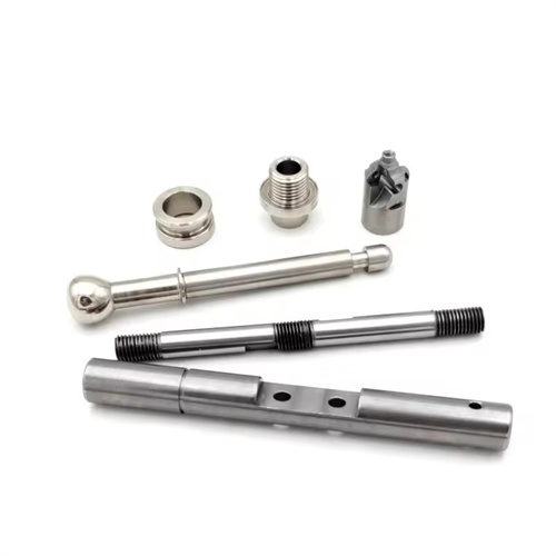
Milling spline shaft
Spline shafts are essential components for torque transmission in mechanical transmissions. By meshing multiple teeth on the shaft with the teeth of the spline sleeve, they offer strong load-bearing capacity, high centering accuracy, and smooth transmission. They are widely used in automotive transmissions, machine tool spindles, and construction machinery. The key to milling spline shafts is ensuring the tooth profile accuracy (tooth profile error ≤ 0.015mm), cumulative pitch error (≤ 0.02mm/100mm), and symmetry of each tooth (≤ 0.01mm). This is particularly true for rectangular and involute splines, where the flank fit accuracy directly impacts transmission efficiency. For example, a pitch error exceeding 0.03mm on an automotive transmission spline shaft can cause shifting problems or poor power transmission. Therefore, when milling spline shafts, appropriate machining methods and process parameters must be selected based on the spline type, accuracy grade, and production batch size.
The milling method for spline shafts depends on the structural type and precision requirements. Forming and generating methods are commonly used for milling rectangular spline shafts. The forming method uses a forming milling cutter that matches the spline tooth profile to mill one tooth at a time. All teeth are then indexed sequentially using an indexing head. This method is suitable for single-piece, small-batch production. Tooth profile accuracy depends on the precision of the milling cutter (AA-grade forming milling cutters are required). The cumulative pitch error after machining is ≤0.03mm. The generating method (hobbing) uses a spline hob to continuously machine all teeth through a generating motion between the hob and the workpiece. This method is suitable for mass production and is 5-10 times more efficient than the forming method. The cumulative pitch error can be controlled within 0.015mm. The generating method must be used for milling involute spline shafts. Using an involute spline hob, machining is based on the principle of involute formation to ensure tooth conjugation. Post-milling, tooth profile modification (such as tip rounding and root filleting) is required to reduce stress concentration. An automotive parts factory used the hobbing method to process rectangular spline shafts, which increased production efficiency by 8 times and significantly improved the consistency of tooth pitch.
Tool selection and installation accuracy significantly impact spline quality. Rectangular spline milling cutters are standardized by tooth number and module series. When selecting a cutter, it must match the number of teeth and tooth width of the spline. For example, to machine an 8-tooth, 2mm module spline shaft, an 8-tooth forming cutter of corresponding specifications should be used. The cutter material should be high-speed steel (W18Cr4V) or carbide (YT15). The former is suitable for low-speed fine milling, while the latter is suitable for high-speed rough milling. The module and pressure angle of the involute spline hob must match the spline parameters (e.g., a 2mm module and a 30° pressure angle). The hob’s helix angle must be compensated by tilting the toolholder to ensure tooth profile accuracy. When installing the cutter, ensure that the axis is parallel to the workpiece axis, with a parallelism error of ≤0.01mm/m and radial runout of ≤0.005mm. Failure to do so will result in excessive tooth profile error. For precision spline shafts, the cutter must be dynamically balanced (to a G2.5 balancing accuracy) to prevent vibration during high-speed rotation. A machine tool factory reduced the tooth direction error of the spline shaft from 0.02mm/m to 0.008mm/m by installing high-precision tools, meeting the requirements of precision transmission.
Spline shaft clamping and indexing must ensure machining accuracy. Rigid spline shafts (aspect ratio ≤ 5) can be clamped with a double ejector. The center holes at both ends must be ground (roundness ≤ 0.005mm), and the tailstock center must apply appropriate clamping force (3-5kN) to prevent axial movement of the workpiece. Slender spline shafts (aspect ratio > 10) require a steady rest support. The support block should be made of wear-resistant cast iron, with a contact pressure of 0.02-0.03MPa on the workpiece to prevent bending and deformation. Indexing positioning is achieved through an indexing head, with an indexing accuracy of ≤±15″. For multi-tooth splines (such as 16 teeth), an optical indexing head or CNC indexing system is required to ensure the position consistency of each tooth. Before processing, the workpiece radial runout (≤0.01mm) and axial runout (≤0.005mm) must be corrected, and the coaxiality between the workpiece outer circle and the indexing head axis must be corrected with a dial indicator (≤0.01mm). A construction machinery factory uses a CNC indexing head to process a 12-tooth spline shaft. The indexing error is controlled within ±5″, and the cumulative pitch error is ≤0.01mm.
Optimizing cutting parameters and process routes requires a balance between efficiency and quality. When rough milling spline shafts, maintain a cutting speed of 60-100 m/min (steel) or 40-60 m/min (cast iron), a feed rate of 0.1-0.2 mm/r, and a back cut of 1-2 mm. Emulsion cooling is used to quickly remove excess stock. For fine milling, increase the speed to 100-150 m/min, reduce the feed rate to 0.05-0.1 mm/r, and use a back cut of 0.1-0.3 mm. Extreme-pressure cutting oil is used to ensure high-quality tooth surfaces. The process follows a “rough milling – tempering – finish milling” process: After rough milling, a 0.5-1mm finishing allowance is retained, and then tempering (40Cr steel 220-250HB) is performed to relieve stress. Before finish milling, the key tooth dimensions are checked and cutting parameters adjusted based on the allowance. After finish milling, deburring is performed (tooth top chamfer C0.2-C0.5) to prevent scratches on the spline hub during assembly. For high-precision spline shafts, grinding is performed after finish milling, reducing tooth surface roughness to Ra0.4μm and tooth profile error to ≤0.005mm. By optimizing the process, an aircraft engine manufacturer has extended the service life of spline shafts by 30% and increased transmission efficiency to over 98%.
Quality inspection and defect prevention for spline shafts must be carried out throughout the entire manufacturing process. Inspections include: checking overall accuracy with a spline gauge (all teeth must pass with a go gauge, no teeth must pass with a stop gauge); measuring pitch error with a pitch gauge, with a single pitch error of ≤0.01mm; checking the tooth profile with a tooth profile gauge to ensure compliance with standards; and checking the symmetry of the key teeth with a dial indicator, with an error of ≤0.01mm. Common defects and preventative measures: Tooth profile asymmetry is often caused by skewed tool installation, requiring recalibration of the tool axis; out-of-tolerance pitch may be due to indexing head error, requiring regular calibration of indexing accuracy; surface roughness is often due to tool wear, requiring timely sharpening or replacement. Important spline shafts also require hardness testing (220-250 HB after quenching and tempering) and magnetic particle inspection to ensure the absence of defects such as cracks. Through rigorous testing, an automotive transmission manufacturer has increased the spline shaft qualification rate from 90% to 99.5%, significantly reducing after-sales failures.