Milling inner spherical surface
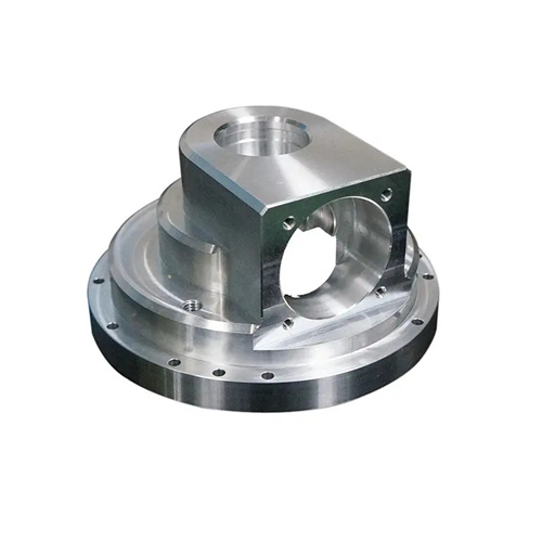
Milling internal spherical surfaces is a machining process requiring high precision. It is commonly used to manufacture concave spherical surfaces in parts such as bearing seats, valve spools, and hydraulic components. It requires ensuring the surface’s roundness (≤0.01mm), surface roughness (Ra ≤1.6μm), and positional accuracy relative to relevant datums (e.g., perpendicularity to the end face ≤0.02mm). The radius of curvature of an internal spherical surface typically ranges from 10 to 500mm, and machining difficulty increases with diameter. Especially when the depth-to-diameter ratio exceeds 0.5, tool entry and feed are limited, leading to interference and blind spots. For example, when machining an internal spherical surface with a diameter of 100mm and a radius of curvature of 60mm, improper tool selection can result in tool marks at the bottom of the surface, compromising sealing performance. Therefore, a comprehensive machining plan for internal spherical surface milling requires consideration of the surface parameters, workpiece material, and precision requirements.
The selection and geometric design of internal spherical milling cutters are crucial to machining quality. Commonly used internal spherical milling cutters include ball-end milling cutters, annular milling cutters, and form milling cutters. Ball-end milling cutters are highly versatile and suitable for machining internal spherical surfaces of any curvature radius. Their diameter is typically 0.5-0.8 times the spherical radius (e.g., for a 60mm radius, a φ30-φ48mm ball-end milling cutter is used). The tool material is selected based on the workpiece material: cemented carbide (such as YT15 and YW2) is used for steel, YG8 for cast iron, and high-speed steel for non-ferrous metals. Annular milling cutters are suitable for machining large-diameter internal spherical surfaces (≥200mm). They achieve spherical shaping through the rotation of the annular cutting edge, resulting in a 3-5 times higher efficiency than ball-end milling cutters, but they must precisely match the spherical radius of curvature. Form milling cutters are only suitable for internal spherical surfaces with a fixed curvature in mass production. Their cutting edge shape perfectly matches the spherical contour, achieving machining accuracy up to IT7. The tool’s rake angle is 5°-10°, and its relief angle is 8°-12° to reduce cutting resistance and avoid interference with the spherical surface. The cutting edge is finely ground, with a radius of ≤0.05mm to prevent tearing of the machined surface. A hydraulic component manufacturer used a φ40mm carbide ball-end milling cutter to machine the inner spherical surface, reducing surface roughness from Ra3.2μm to Ra0.8μm, with roundness error within 0.008mm.
The method for milling internal spherical surfaces depends on the equipment and surface accuracy. When machining internal spherical surfaces on a CNC milling machine, the tool’s spatial trajectory is controlled through three-dimensional linkage. The tool path is generated according to the parametric equations of the sphere (x=Rsinθcosφ, y=Rsinθsinφ, z=Rcosθ). With a feed rate of 0.1-0.2mm/rev and a cutting speed of 80-120m/min, it is suitable for machining high-precision, complex spherical surfaces. When machining on a conventional milling machine, an indexing head or specialized fixture is required to provide rotary feed of the workpiece, coordinated with the radial feed of the tool to form the spherical surface. During operation, the feed rate must be continuously adjusted through trial cutting to ensure uniform curvature. For hemispherical internal spherical surfaces, a “layered milling method” can be used: feed is applied layer by layer from the edge of the sphere toward the center, with a cutting depth of 0.5-1mm per layer. Finally, a ball-end milling cutter is used for finishing to reduce tool load and deformation. During machining, the tool axis must be aligned with the sphere’s center, with a coaxiality error of ≤0.01mm. Otherwise, ellipticity errors will occur on the sphere. When machining the inner surface of a hemispherical valve core, a valve manufacturer adjusted the fixture to align the tool axis with the sphere’s center, reducing the ellipticity error from 0.03mm to 0.005mm, meeting sealing requirements.
The optimization of cutting parameters must take into account both machining efficiency and spherical surface quality. When rough milling the inner sphere, the main goal is to remove the allowance, with a cutting speed of 60-100m/min, a feed rate of 0.2-0.3mm/r, and a back cut depth of 1-2mm. Emulsion cooling (concentration 10%) is used to promptly flush away chips to avoid accumulation. When fine milling, surface accuracy must be guaranteed. The cutting speed is increased to 100-150m/min, the feed rate is reduced to 0.1-0.15mm/r, and the back cut depth is 0.1-0.3mm. Extreme pressure cutting oil is used to enhance lubrication and reduce tool wear. For high-strength materials (such as 40CrNiMo), the cutting speed needs to be reduced (50-80m/min) and the tool back angle needs to be appropriately increased (10°-15°) to prevent work hardening. The selection of cutting parameters also needs to consider the spherical surface’s radius of curvature. For spherical surfaces with a small radius of curvature (<50mm), high speeds and low feeds are recommended to avoid tool vibration. For spherical surfaces with a large radius of curvature (>200mm), the feed rate can be increased to shorten machining time. By optimizing these parameters, a heavy machinery plant reduced machining time for a φ500mm internal spherical surface from 4 hours to 2.5 hours, while still achieving satisfactory surface quality.
Strict quality inspection and error correction must be performed on the inner spherical surface. During machining, the spherical profile must be checked with a sample through the light, with a gap of ≤0.01mm. The spherical diameter must be measured with an internal diameter dial indicator or spherometer, with an error of ≤±0.02mm. Roundness must be checked with a roundness tester to ensure compliance with design requirements. Common defects and correction methods: Sharp edges on the spherical surface are often caused by excessive feed or incorrect tool radius compensation, requiring feed reduction or recalibration of the tool radius. Chatter marks on the surface are often caused by insufficient machine tool rigidity, requiring reduced cutting speeds or increased support. Localized depressions may indicate uneven tool wear, requiring timely sharpening. For inner spherical surfaces with extremely high precision requirements (such as precision bearing seats), grinding is required. Using a grinding tool matched to the spherical surface and chromium oxide as the abrasive, the surface roughness can reach Ra 0.02μm and a roundness error of ≤0.003mm. Through comprehensive testing and correction, a precision instrument manufacturer has increased the pass rate for inner spherical surfaces from 85% to 99%, ensuring part assembly accuracy and performance.