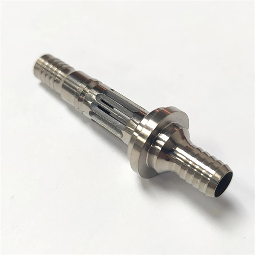
Main parameters of cylindrical worm
A cylindrical worm is the active component in a worm drive. It meshes with a worm wheel to achieve staggered transmission (typically with a 90° intersecting angle ). It features a high transmission ratio ( 10-80 ), compact structure, and smooth operation. It is widely used in machine tool feed mechanisms, lifting equipment, precision instruments, and other fields. Its key parameters include module, pressure angle, lead angle, number of turns, and diameter coefficient. These directly determine the worm’s tooth profile, strength, and transmission efficiency. For example, a worm with a module m = 5 mm and number of turns z₁ = 2 , when meshing with a worm wheel, has a transmission ratio i = z₂/z₁ ( where z₂ is the number of worm wheel teeth). If z₂ = 40 , then i = 20 , achieving a reduction transmission. Therefore, understanding the key parameters of a cylindrical worm and their interrelationships is crucial for worm design, processing, and assembly.
The module ( m ) is a fundamental parameter of cylindrical worm gears, determining the size and strength of the tooth profile. The module is the ratio of the worm’s axial pitch, p , to π ( m=p/π ). National standards specify a standard module series (such as 1 , 1.25 , 1.6 , 2 , 2.5 , 3.15 , 4 , 5 , 6.3 , and 8mm ). Designs should select from this standard series to ensure standardization of both the tool and the worm gear. The larger the module, the greater the worm’s tooth thickness and root strength. For example, an m=8mm worm has a root thickness of approximately 4.5mm and can transmit more than four times the torque of a 4mm worm . The module must match the worm diameter; typically, the module m should be ≥ d₁/30 ( d₁ is the worm pitch diameter) to avoid fine teeth (which can lead to insufficient root strength). When designing a feed worm, a machine tool manufacturer selected a module of m=5mm based on the transmission torque of 200N · m . This not only met the strength requirements but also reduced the processing difficulty.
The pressure angle (α) determines the degree of inclination of the worm tooth profile and influences meshing performance. The pressure angle of a cylindrical worm typically refers to the tooth profile angle of the shaft cross-section. The standard pressure angle is α = 20° (for standard worms). For heavy-duty worms (such as those used in lifting equipment) , an α = 25° can be used to increase tooth root strength; for precision transmissions (such as instrumentation) , an α = 15° can be used to reduce meshing friction. The pressure angle directly affects the worm tooth profile dimensions: addendum height hₐ = m , root height h = 1.2 m , and total tooth height h = 2.2 m . These dimensions are calculated based on the module. The pressure angle must be equal to that of the worm wheel; otherwise, meshing interference will occur. For example, a worm with α = 20° must be paired with a worm wheel with α = 20° . The meshing backlash should be controlled within 0.05-0.1 mm (depending on the accuracy grade). A certain lifting machinery factory uses a worm with α=25°, which increases the tooth root bending strength by 20%, meeting the heavy-load transmission requirements.
The number of starts ( z₁ ) and the lead angle (γ) jointly influence the transmission efficiency and speed of a worm gear. The number of starts refers to the number of helical threads on the worm. Standard starts are 1 , 2 , 4 , and 6. A higher number of starts increases the transmission efficiency (single-start worms have an efficiency of approximately 0.7-0.8 , while four -start worms can reach 0.9 ), but also increases machining difficulty. The relationship between the number of starts and the lead angle is tanγ = z₁m/d₁ ( d₁ is the pitch circle diameter). A larger lead angle results in a steeper helix and faster transmission speed. For example, a worm with z₁=4 , m=4mm , and d₁=40mm has a tanγ of 4×4/40=0.4 , γ≈ 21.8° , and a lead of s=z₁m=16mm , resulting in a feed rate four times faster than a single-start worm ( s=4mm ) . However, excessive lead angles ( >30 °) can reduce worm stiffness, so the lead angle is typically kept between 3° and 30°. A precision instrument uses a single-start worm (γ = 5°). Although this has lower efficiency, it offers smooth transmission and meets the precision requirements of the fine-tuning mechanism.
The pitch diameter ( d₁ ) and diameter coefficient ( q ) are key parameters for ensuring worm standardization. The pitch diameter is the diameter where the tooth thickness and space width of the worm are equal. The standard specifies a series of pitch diameters that match the module (e.g., for m=2mm , d₁=18 , 22.4 , and 28mm ). The diameter coefficient q = d₁/m and is a dimensionless parameter (e.g., for d₁=20mm and m=2mm , q=10 ). A smaller q value indicates a more slender worm (less rigidity); a larger q value indicates a more robust worm (more rigidity). Typically, q=8-16 . The pitch circle diameter must match the worm gear’s midplane diameter, ensuring a meshing center distance a = (d₁ + d₂)/2 ( d₂ is the worm gear pitch circle diameter). For example, if a = 100 mm and d₁ = 40 mm , then d₂ = 160 mm . A reducer manufacturer has improved the interchangeability of worms and worm wheels and reduced production costs by standardizing d₁ and q values.
Other important worm parameters include the tip diameter, root diameter, and lead. The tip diameter, dₐ₁, is calculated as d₁ + 2hₐ = d₁ + 2m (e.g., if m = 3mm , d₁ = 30mm , or dₐ₁ = 36mm ). This is the maximum diameter of the worm’s outer diameter and is required to ensure top clearance with the worm wheel ( c = 0.2m ). The root diameter, d₁ , is calculated as d₁ – 2h₁ = d₁ – 2.4m (e.g., for the worm mentioned above, d₁ = 30 – 7.2 = 22.8mm ). This determines the tooth root strength and requires verification calculations (bending strength and contact strength). The lead, s = z₁pₐ = z₁πm ( pₐ is the axial pitch), is the axial distance the worm travels during one rotation. For example, if z₁ = 2 and m = 5mm , s = 2 × π × 5 ≈ 31.4mm . Lead accuracy must be controlled within ±0.02mm/100mm to prevent transmission errors. By controlling lead accuracy, a machine tool manufacturer has reduced the feed error of worm drives from 0.05mm/1000mm to 0.01mm, meeting precision machining requirements.
The selection of worm parameters requires a comprehensive consideration of transmission performance and manufacturing feasibility. For high-speed transmissions (speeds > 1000 rpm ), a multi-start worm ( z₁=4-6 ) and a large lead angle (γ =15°-30° ) are recommended to improve efficiency (≥ 0.9 ). For low-speed, heavy-load transmissions (speeds < 300 rpm ), single- or double-start worms ( z₁=1-2 ) and a small lead angle (γ =3°-10° ) are used to ensure strength. The module and diameter should be calculated based on the transmitted power: for power P ≤ 10 kW , m = 2-5 mm ; for power P = 10-50 kW , m = 5-10 mm ; for power P > 50 kW , m > 10 mm . After determining the parameters, verify that the center distance a is reasonable (typically a = 50-500 mm ) to avoid overly large or undersized structures. A wind power equipment manufacturer selected a worm with m=8mm , z₁=2 , q=10 and a center distance a=200mm to meet the power requirements of 30kW , which not only meets the strength requirements but also facilitates installation.