Turning of cast iron cross joints
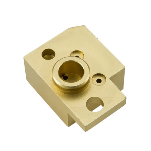
Cast iron cross joints, a key component for achieving multi-directional connections in mechanical transmission systems, are widely used in automotive steering mechanisms, hydraulic piping for construction machinery, and other applications. The quality of their turning directly impacts the equipment’s assembly precision and operational reliability. These parts typically feature four connecting ports at 90° angles to each other. High coaxiality between the inner and outer diameters of these ports is required (generally ≤0.03mm), and perpendicularity between the end faces and the axis must be controlled within 0.02mm/m. Due to the brittleness of cast iron and the asymmetric port structure, turning can easily generate cutting force fluctuations, leading to workpiece vibration and, in turn, reduced machining accuracy. Therefore, a refined machining plan is essential.
Optimizing the clamping method is the primary step in ensuring the stability of cast iron cross joint processing. Due to the symmetrical structure of the cross joint, a four-jaw single-action chuck can be used for clamping. By adjusting the position of the four jaws, the axis of the workpiece and the axis of the spindle can be made to coincide, and the external cylindrical runout can be corrected to within 0.01mm using a dial indicator. For cross joints with flanges, auxiliary supports must be provided on the flange end faces, and an adjustable center point must be used to support the center hole of the end face to prevent axial movement of the workpiece during cutting. In addition, excessive clamping that may cause deformation of the workpiece should be avoided during clamping. A 1-2mm thick copper sheet can be inserted into the contact area between the jaws and the workpiece to enhance friction, buffer the clamping force, and protect the workpiece surface from being pinched.
Tool selection and cutting parameter setting must take into account both machining efficiency and surface quality. YW1 carbide tools are recommended for rough turning. They have high bending strength and wear resistance and are suitable for cutting brittle materials such as cast iron. The tool rake angle is 5°-8° and the back angle is 6°-10° to reduce cutting resistance. When rough turning the outer circle, the spindle speed is controlled at 400-600r/min, the feed rate is 0.3-0.5mm/r, and the cutting depth is 2-3mm to quickly remove the blank allowance. When fine turning, use YT15 coated tools, and use the low friction coefficient of the coating to reduce the cutting temperature. The spindle speed is increased to 800-1000r/min, the feed rate is reduced to 0.1-0.15mm/r, and the cutting depth is 0.1-0.3mm to ensure that the outer circle surface roughness reaches Ra1.6μm. For internal hole turning, a solid carbide internal hole turning tool is selected, and the tool shank diameter is selected according to the internal hole size (generally 0.7-0.8 times the internal hole diameter) to ensure sufficient rigidity and avoid tool shank vibration.
The process layout should follow the principle of “roughing first, finishing second, primary work first, secondary work second” to gradually improve part accuracy. First, machine the cross joint’s reference outer diameter and end face. Using this as a positioning reference, machine the first port’s inner bore. After rough turning the inner bore, allow a 0.5-0.8mm allowance for finish turning. Next, flip the workpiece over and, using the machined inner bore as a reference (using a mandrel for positioning), machine the outer diameter and inner bore of the opposite port, ensuring coaxiality. The other two perpendicular ports are then machined in sequence. After each clamping, use a dial indicator to recalibrate to ensure the perpendicularity error between the port axis and the reference axis does not exceed 0.02mm. Radius transitions at the ports should be machined in a single pass using a forming turning tool to avoid dimensional inconsistencies caused by manual grinding. After rough turning, stress relief treatment (at 200-250°C for 4 hours) should be performed to eliminate machining stresses and prevent deformation during subsequent finish turning.
Precision detection and error compensation are key steps to ensure the quality of cross joints. After each process is completed, it is necessary to use the corresponding measuring tools for inspection: the outer diameter is measured with a micrometer, and the measurement is repeated 3 times to take the average value to ensure that the dimensional tolerance is controlled within the h6 range; the inner hole size is detected with an inside diameter dial indicator, focusing on the hole roundness and cylindricity; the coaxiality error is measured by the dial gauge method, the workpiece is placed on the V-shaped iron, and the workpiece is rotated one circle. The difference in the maximum reading of the dial gauge is the coaxiality error. If an out-of-tolerance problem is found, it is necessary to analyze the cause and adjust the process parameters: if the dimensional deviation is caused by tool wear, the tool should be replaced and re-calibrated in time; if the precision out-of-tolerance is caused by clamping deformation, the clamping force distribution needs to be optimized. For mass-produced cross joints, a special inspection fixture can be used for rapid inspection. Four locating pins are set on the inspection fixture to match the reference hole. The port clearance is checked with a plug gauge to improve the inspection efficiency.